
Design For Additive Manufacturing
Discover effective strategies for optimising prevalent design elements, including bridges, overhangs, pins, and vertical axis holes, specifically tailored for Additive Manufacturing.
What is the approach to designing for FDM printing?
Bridging
In Fused Deposition Modeling (FDM), bridging arises when the printer is tasked with printing across gaps between two support or anchor points. Due to the absence of a foundation, the initial layer being printed lacks support, resulting in material sagging. Bridging instances commonly manifest within horizontal-axis voids present in object walls or within the upper layer (roof) of hollow components.
One approach involves minimizing the bridge span; however, the effectiveness of this depends on the specific design constraints of the part. Another method to mitigate sagging is the incorporation of support structures. These supports provide a provisional platform for constructing the bridging layer. Upon completion of the print, the support material is removed, although it may leave residual marks or damage on the final part’s surface where the support was initially attached.

Important design consideration: Given the inherent characteristics of Fused Deposition Modelling (FDM), the presence of sagging or imprints from support material is inevitable to some degree, unless the bridge span is less than 5mm. Achieving a smooth, level surface may necessitate advanced approaches, such as dividing the design into distinct parts or implementing post-processing techniques.
Vertical axis holes
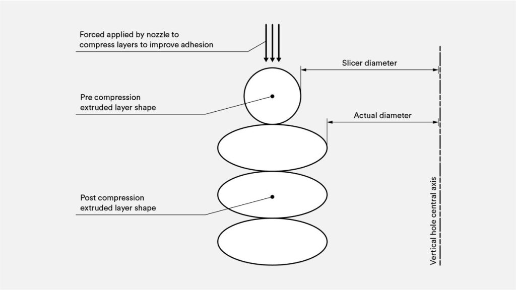
Fused Deposition Modeling (FDM) frequently results in the production of vertically oriented holes that are smaller than intended. The printing procedure for such holes and the factors contributing to the reduction in their diameter can be succinctly outlined as follows:
- As the nozzle prints the perimeter of a vertical axis hole, it compresses the newly printed layer down onto the existing build layers to help improve adhesion.
- The nozzle’s compressing force deforms the extruded round layer shape from a circle into a wider, flatter shape (see image below).
- This increases the area of contact with the previously printed layer, improving adhesion but widening the extruded segment.
- This causes a decrease in the hole diameter being printed. This decrease can be an issue, particularly when printing small-diameter holes, whereby the effect is greater due to the ratio of hole diameter to nozzle diameter.
The degree of undersizing is contingent upon factors such as the specific printer, slicing software utilized, hole dimensions, and the chosen material. While slicing programs typically address the reduction in diameter for vertical axis holes, the precision can fluctuate. Attaining the desired accuracy may necessitate multiple test prints. In instances where a heightened level of precision is imperative, post-printing hole drilling may be a requisite step.
Critical design consideration: When the precise diameter of the vertical axis hole is crucial, it is advised to print it with a slightly smaller size and subsequently use drilling to achieve the accurate diameter.
Overhangs
Challenges related to overhangs represent a prevalent concern in Fused Deposition Modeling (FDM) print quality. Overhangs manifest when the current layer of material lacks complete support from the layer beneath it. Similar to bridging, insufficient support from the underlying surface can lead to compromised layer adhesion, as well as issues such as bulging or curling.
Depending on the material, it is typically feasible to print an overhang up to a 45° angle without sacrificing quality. At this angle, the newly printed layer receives support from 50% of the preceding layer, facilitating adequate stability and adhesion for subsequent layers. Beyond a 45° angle, external support becomes essential to prevent the newly printed layer from sagging and deviating away from the nozzle.
Another challenge encountered during the printing of overhangs is the issue of curling. As the newly printed layer extends beyond the overhang, it progressively becomes thinner at the edge. This variance in cooling rates results in differential cooling, leading to upward deformations.
Key design consideration: Mitigate overhang limitations by implementing support structures for wall angles exceeding 45°. Larger overhangs requiring support may result in visible marks on the final surface, unless post-processing is applied.
Vertical pins
Vertical pins are commonly produced using Fused Deposition Modeling (FDM) when there is a need for part assembly or alignment. It is imperative to have a comprehensive understanding of the precise dimensions of vertical pins that FDM can reliably print, particularly given their frequent functional significance.
For pins with a diameter exceeding 5mm, a combination of perimeter and infill printing is employed to establish a robust connection with the overall print structure. Conversely, pins with a diameter less than 5mm consist solely of perimeter prints without infill. This configuration introduces a potential weakness in the connection between the pin and the surrounding print, rendering it susceptible to breakage. In the most adverse situations, smaller pins may fail to print altogether due to insufficient material for proper adhesion with the newly printed layers.

Accurate printer calibration, encompassing key parameters such as optimal layer height, print speed, and nozzle temperature, frequently diminishes the probability of small-pin failure. Incorporating a radius at the pin’s base serves to eliminate it as a stress concentration point, enhancing overall strength. In instances where critical pins measure less than 5mm in diameter, utilizing an off-the-shelf pin inserted into a printed hole may present an optimal solution.
Critical Design Note: In instances where your design incorporates pins with a diameter smaller than 5mm, it is advisable to incorporate a modest fillet at the pin’s base. For applications demanding heightened functionality, contemplate integrating a designated hole in the design corresponding to the pin’s location. Subsequently, drill the hole to the appropriate size and insert a readily available off-the-shelf pin for optimal performance.
Tips for advanced FDM design
When utilizing Fused Deposition Modeling (FDM) for printing, it is advisable to strategize ways to minimize the necessity for support structures. This involves thoughtful consideration of the part’s orientation and the specific direction in which the part is constructed on the build platform.
Splitting your model
Dividing a model can frequently streamline its intricacy, resulting in cost and time savings. Overhangs, necessitating substantial support, can be eliminated by strategically segmenting a complex shape for separate printing. Optionally, these sections can be seamlessly assembled post-printing through adhesive bonding.

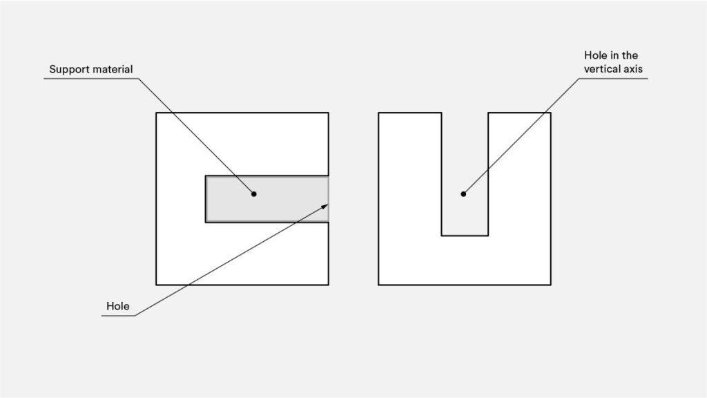
Hole orientation
To mitigate the need for support structures in holes, consider adjusting the print orientation. Support removal in holes aligned along the horizontal axis can pose challenges, yet rotating the build direction by 90° can obviate the necessity for support. When dealing with components featuring various holes in different orientations, it is advisable to prioritize addressing blind holes first, followed by those with progressively smaller to larger diameters, taking into account the criticality of hole size.
Build direction
Given the anisotropic characteristics inherent in FDM printing, a comprehensive grasp of a component’s intended application and its construction is imperative for achieving design success. The weakness in one direction of FDM components is inherent, stemming from the layer orientation and necessitating careful consideration during the design process.

The structural vulnerability arises due to the absence of uninterrupted material pathways and the stress concentration resulting from each layer joint. The layers, shaped as round-ended rectangles, form joints that manifest as small valleys, leading to a concentration of stress and an increased susceptibility to cracking.
